Uni-Housing™ Pressurized Enclosures
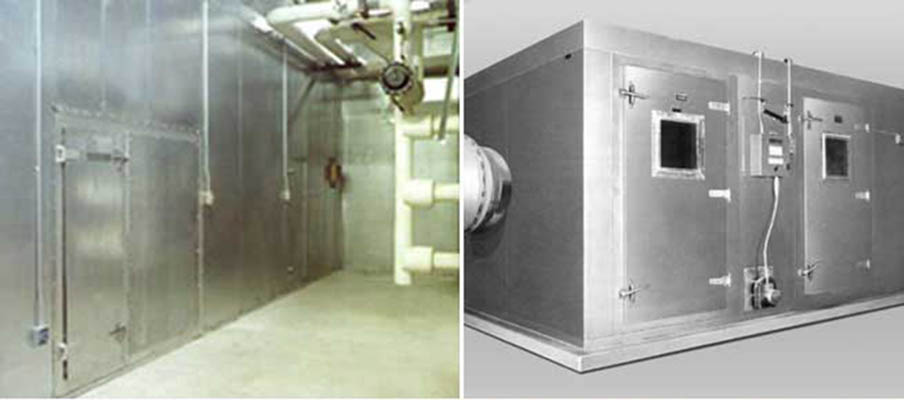
Uni-Housing enclosures are an excellent choice for enclosing many types of HVAC equipment. Their modular panel construction creates a strong, self-supporting, and long-lasting enclosure that can be used for both indoor and outdoor applications. They are designed to have low leakage, provide excellent thermal and acoustical control, and facilitate easy on-site assembly. Depending upon the application and size of the enclosure, McGill AirSilence can deliver finished units or subassemblies to the job site.
MATERIAL TYPES AND THICKNESSES
Type SL and Type TG Uni-Housing panels are the basic building block of all Uni-Housing pressurized enclosures. The standard material for both the outer shell and inner liner is galvanized steel. It can be specified as either solid or perforated and has a minimum G-60 zinc coating. The perforated steel has a 23 percent open area. Many different material and gauge combinations of outer shell and inner liner can be selected, with the inner liner being either solid or perforated.
Both SL and TG acoustical panels are available in a standard 4-inch thickness. A 2-inch thickness is optional, with other thicknesses by special order. Standard panel widths are 24 inches and 36 inches, with standard lengths up to 12 feet. Other widths and longer lengths are also available through special order. For most enclosures, at least one special-width panel will be required as a fill-in panel to match the specified dimensions of each wall, floor, or roof assembly. Also, in most cases, maximum panel lengths will be determined by the working design pressures.
INSULATION
The standard acoustic/thermal fill material used in Type SL and Type TG panels is 1.55 pcf fiberglass, giving the standard 4-inch panel a value of R-17.
SURFACE BURNING CHARACTERISTICS
The Type SL and Type TG panels meet or exceed stringent fire safety requirements.
Uni-Housing™ Standard Panel Construction
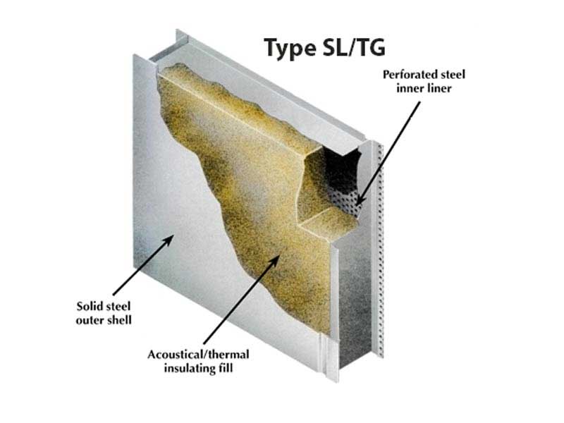
Uni-Housing pressurized enclosures can be constructed from McGill AirSilence's Type SL or Type TG acoustical panel systems. The Type SL and Type TG panels are identical except for their panel joint designs. The Type SL panel has a self-locking (snap-lock) design that offers quick assembly and is used in applications where disassembly is not a primary concern. The Type TG panel has a simple tongue-and-groove design that is recommended when future disassembly and re-erection of the enclosure may be required. Both acoustical panels have a sandwich-type construction consisting of a solid galvanized steel outer shell, acoustical/thermal insulating fill, and a perforated inner liner of galvanized steel. All of the standard wall, door, roof, and floor panels are available with either the snap-lock joint design or tongue-and-groove joint design.
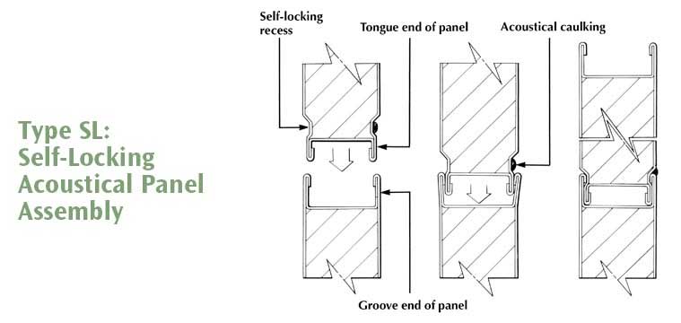
TYPE SL — SNAP-LOCK PANEL SYSTEMS — Permanent installations
Type SL panel systems are not intended for use in projects in which future disassembly and re-erection may be required.
Rapid panel assembly time
The snap-lock feature eliminates the need for joint-to-joint sheet metal screws and speeds assembly.
Visually appealing panel-to-panel joints
The elimination of sheet metal screws at the joings provides an atractive assembled enclosure.
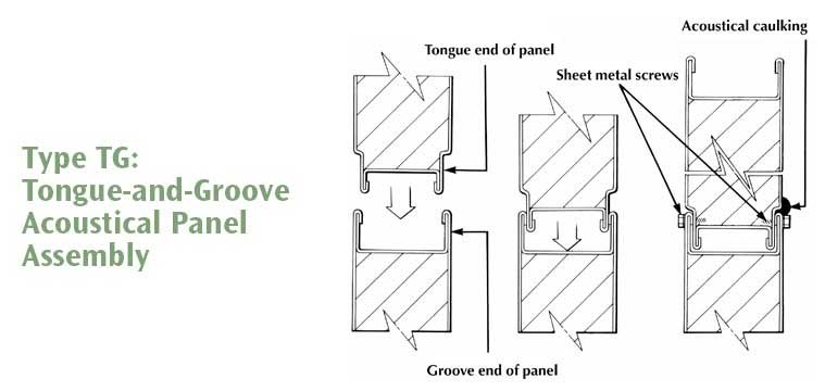
TYPE TG — TONUGE-AND-GROOVE PANEL SYSTEMS — Semi-permanent installations
Type TG panel systems allow future disassembly and re-erection.
Assembly and Installation Sequence of a UniHousing™ Pressurized Enclosure
ACCESS AND ACOUSTICAL DOORS
All panel systems for enclosures and barriers can be furnished with a wide variety of personnel, machinery, and material access doors. Standard access doors are 24 inches wide by 60 inches high. They are insulated and equipped with a minimum of two hinges, two door latches (with inside personnel safety releases), and gasketing. Access doors are available in both right- and left-hand swings, opening in or out.
All panel systems for enclosures and barriers can be furnished with a wide variety of personnel, machinery, and material access doors. Standard access doors are 24 inches wide by 60 inches high. They are insulated and equipped with a minimum of two hinges, two door latches (with inside personnel safety releases), and gasketing. Access doors are available in both right- and left-hand swings, opening in or out.
REMOVABLE ACCESS PANELS
When interior access is required to service or repair equipment, Uni-Housing pressurized enclosures can be fabricated with conveniently located, removable access panels. They use the same construction as the surrounding non-removable panels, but they have a larger-sized outer shell. The larger-sized outer shell allows the use of a self-sealing gasket on its inside perimeter and the use of fasteners to secure the panel in place.
When interior access is required to service or repair equipment, Uni-Housing pressurized enclosures can be fabricated with conveniently located, removable access panels. They use the same construction as the surrounding non-removable panels, but they have a larger-sized outer shell. The larger-sized outer shell allows the use of a self-sealing gasket on its inside perimeter and the use of fasteners to secure the panel in place.
OBSERVATION WINDOWS
Access windows fro pressurized access doors are factory installed with an inner and outer pane of wire-reinforced glass, and have an air space between frames along with an air-tight window seal. Standard size is 12 inches by 12 inches. Other sizes and types are available. Obervation windows can be provided on all doors.
Access windows fro pressurized access doors are factory installed with an inner and outer pane of wire-reinforced glass, and have an air space between frames along with an air-tight window seal. Standard size is 12 inches by 12 inches. Other sizes and types are available. Obervation windows can be provided on all doors.

Typical Installation Sequence for SL and TG Panel Systems
- Locate base channel
- Set corner panels
- Install wall, partition, and door panels
- Add wall trim — outside and inside
- Optional structural steel (as required)
- Add roof panels
- Add roof trim — outside and inside
- Completed acoustical enclosure
FACTORY PREFORMED TRIM AND STRUCTURAL ITEMS
McGill AirSilence supplies a complete line of factory-made trim items for joining and erecting panel members and finishing out the Uni-Housing pressurized enclosure. These include standard trim items as well as optoinal special trim and structural items. All base channel and outside trim is pre-punched during production for #10 by 3/4-inch sheet metal screws on 6-inch centers. No field drilling of these items is required. Pre-punching assures proper location of necessary fasteners. Inside trim is not prepunched in order to allow location of screws at panel joints.
SEALER
UL-Classified United Duct Sealer (water based) is supplied in 10.5 ounce tubes in sufficient quantity to assemble each Uni-Housing enclosure. It is used at the base channels, outside trim, panel joints, and with the inner trim if a pressure differential exists.
FASTENERS
Where required, self-drilling sheet metal screws (#10 by 3/4 inch) are supplied with each Uni-Housing enclosure for assembly of trim. Sheet metal screws are not required for the Type SL panel joint except for occasional support of panels around large openings.
PIECE MARKING
A convenient piece-marking and color-coding system for all Uni-Housing enclosure components is utilized. Each panel carries an identification mark that is keyed to the assembly drawings and indicates its location and function. A color-coding system is used to assure proper panel selection during assembly if more than one Uni-Housing enclosure is to be assembled at the job site.
STRUCTURAL STEEL
Optional structural steel items such as pipe supports, structural beams, angles, and channels may be required in certain Uni-Housing enclosures. In such cases, McGill AirSilence provides this information on the assembly drawings and will supply structural steel components at an additional price.
TECHNICAL INFORMATION
In-depth information about the Uni-Housing pressurized enclosure's thermal, condensation, and acoustical performance, its special design and installation considerations, and its recommended specifications are addressed in McGill AirSilence's publication Engineering Considerations and Recommended Specifications for UNI-HOUSING™ Pressurized Enclosures.
Recommended Specifications for Uni-Housing™ Pressurized Panel Systems
GENERAL
Double-wall (insulated) acoustical enclosures shall be provided as specified on drawings. All panels and components shall be prefabricated and supplied by a nationally-recognized manufacturer with published standards of construction, assembly, and technical performance. The manufacturer shall have produced a standardized, prefabricated panel system for at least 10 years. Construction and performance of the installed system and components shall conform to all specifications listed in this document. The system and components shall not be susceptible to damage from extended exposure to airflow, pressure differentials, vibration, air temperature, or humidity.
JOINT CONSTRUCTION
Enclosure panels shall have either a snap-lock joint construction or a tongue-and-groove joint construction. Panels with snap-lock joint construction shall be such that adjacent panels are held together rigidly with an integral, continuous, self-locking joint on both inside and outside panel surfaces. Panels with tongue-and-groove joint construction will be held together with fasteners such as screws. Neither panel types should require H-connectors, tape, or any other type of additional connectors.
PANEL CONSTRUCTION
- All panels shall be 2 or 4 inches thick, as noted on the drawings, with a solid galvanized steel exterior shell, and a solid or perforated interior galvanized steel shell as noted on the drawings.
- The outer and inner shells shall be tack or spot welded to perimeter and internal longitudinal steel channels and box-end internal closures, in such a manner and spacing that the panel assembly will not fail at the maximum operating loads specified in Structural Performance.
- The outer shell shall be constructed of galvanized steel with a minimum 20-gauge thickness.
- The inner shell shall be constructed of galvanized steel (solid or perforated) with a minimum 22-gauge thickness.
- Perforated material shall have a 23 percent open area.
- All perimeter and internal longitudinal steel channel members shall be constructed of ASTM Type A-653 commercial-quality galvanized steel with a minimum 18-gauge thickness.
- All steel panel surfaces, internal channels, and trim items shall be fabricated from zinc-coated steel with a dipped galvanized coating (minimum G-60 coating class as determined by ASTM A-924) and shall meet all requirements of ASTM A-653 for commercial-quality galvanized carbon steel.
- Where specified on the drawings, septum panels shall consist of a solid galvanized steel sheet (minimum 20-gauge thickness) centrally sandwiched between layers of insulating material and perforated galvanized steel outer sheets (minimum 22-gauge thickness). The solid steel inner sheet shall be framed and sealed so that air does not leak through the enclosure when a pressure differential exists.
COMPONENTS AND INSTALLATION
- All base channels shall be installed on a level concrete curb, the dimensions of which shall be determined from plan-view shop drawings of the system provided by the system manufacturer. Spacing of base channel attachments shall be as outlined in the manufacturer's standard details of assembly.
- All assembly trim items shall be constructed of hot-dipped galvanized steel (minimum 18-gauge thickness) and furnished in standard lengths to be field cut to the required dimensions. Spacing of sheet metal screws, application of duct sealant, and positioning of trim shall be in accordance with the manufacturer's published erection and installation details.
- All mechanical joints and external trim items shall be sealed with a UL-Classified duct sealant in accordance with Section 4 or 5. In order to show that joints have been sealed properly, enough sealant shall be used so that excess sealant is extruded from all completed external joints.
- For enclosures to be installed indoors, joints and trim shall be sealed with United Duct Sealer (Water Based), formulated to withstand temperatures from -25°F to +200°F. Sealant shall be formulated such that surface preparation or solvent cleaning is not necessary. Sealant shall have a UL Classification marking with flame spread of 5 and smoke developed of 0 when applied to 18-gauge galvanized steel or inorganic reinforced cement board, both at a coverage of 31 square feet per gallon. Sealant shall exceed 500 hours without becoming brittle under ASTM-D572 test conditions (oxygen bomb).
- For enclosures to be installed indoors and outdoors, joints and trim shall be sealed with Uni-Weather solvent-based duct sealant that is a neoprene-phenolic mastic formulated to withstand temperatures from -20°F to +300°F. Sealant shall be formulated such that surface preparation or solvent cleaning is not necessary. Sealant shall have a UL Classification marking with a flame spread of 5 and smoke developed of 0 when applied to 18-gauge galvanized steel and a flame spread of 5 and smoke developed of 5 when applied to inorganic reinforced cement board, both at a coverage of 53 square feet per gallon. Sealant shall exceed 1,000 hours under ASTM-D572 test conditions (oxygen bomb) without becoming brittle and 500 hours in QUV accelerated-exterior-aging apparatus without degradation (under ASTM-C732 test conditions).
- Acoustical personnel access doors shall be provided where specified on drawings and shall be 24 inches wide by 60 inches high unless otherwise indicated. All doors shall be the same nominal thickness as the adjacent panels. All access door panels and doors shall be constructed with an 18-gauge solid inner and outer shell. Each door shall have a minimum of two ball-bearing hinges and two wedge-lever door latches. All levers shall be installed to open against the air pressure differential. Doors shall seat against neoprene gasket materials, installed around the entire perimeter of the door frame in such a manner that door operation will provide direct compression with no sliding action between the door and gasket.
- Where shown on drawings, acoustical doors shall be furnished with windows, which are composed of double-glazed layers of wire-reinforced safety glass, separated by an air space, and sealed against acoustical and air leakage by interior and exterior rubber seals. Windows shall be 12 inches wide by 12 inches high unless otherwise indicated.
- Openings for pipe and conduits shall be field cut to ensure proper positioning. All framing members, collars, and bellmouth fittings shall be insulated, welded, and sealed according to the manufacturer's published installation details.
STRUCTURAL PERFORMANCE
- The entire enclosure shall be designed by the manufacturer to be self supporting. Where roof spans and wall loadings require additional structural strength, it shall be provided by heavier panel skins, additional internal longitudinal reinforcing members, or additional structural members and necessary supporting pipe columns. The installer shall furnish and install all structural members and pipe columns according to the drawings and published installation details provided by the manufacturer.
- The finished enclosure shall be able to withstand a positive internal static pressure of ( ) inches wg and a negative internal static pressure of ( ) inches wg. Installations subjected to the effects of weather shall be able to withstand a wind loading of ( ) pounds per square foot.
- Under the conditions specified in the previous section, the assembled structure shall not exhibit any panel joint deflections in excess of L/200, where L is the unsupported span length of any panel section within the completed enclosure.
ACOUSTICAL PERFORMANCE
- The manufacturer shall provide certified testing data obtained from an acoustical laboratory, listing sound absorption and transmission loss characteristics of the enclosure. When requested by the engineer, the manufacturer shall arrange to have a copy of all pertinent acoustical laboratory reports forwarded directly from the laboratory to the engineer.
-
When tested according to ANSI/ASTM C423 or a subsequent version of the standard, the enclosure shall have minimum sound absorption coefficients, as shown in the table below, in the 1/3 octave band center frequencies. The coefficients used shall be those reported by the acoustical laboratory.
Sound Absorption Coefficients Octave Band (Hz) 125 250 500 1,000 2,000 4,000 1K 2K 4K NRC 4-inch panel construction 4-inch panel const. 0.63 1.09 1.17 1.08 1.03 0.97 1.09 2-inch panel construction 2-inch panel const. 0.22 0.64 1.06 1.06 0.98 0.87 0.94 -
When tested according to ASTM E90 or a subsequent version of this standard, the enclosure panel shall have minimum airborne sound transmission losses in the combined full octave band center frequencies as listed below:
Sound Transmission Losses Octave Band (Hz) 125 250 500 1,000 2,000 4,000 1K 2K 4K STC for 4-inch panels 16 24 35 45 53 58 37 for 2-inch panels 18 21 29 38 49 55 33
THERMAL PERFORMANCE
- Insulating materials used in all prefabricated enclosure panels shall have the following maximum thermal conductances at a mean temperature of 75°F: 0.06 BTU per hour per square foot per °F (for 4-inch panels) and 0.12 BTU per hour per square foot per °F (for 2-inch panels).
Uni-Housing™ Pressurized Enclosure Applications
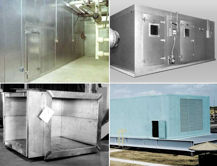
Typical Applications
- Built-up air handling and fan system enclosures
- Air conditioning equipment enclosures
- Outside air intake plenums
- Supply/return air handling and fan system plenums
- Large rectangular duct systems fabricated from Uni-Housing panels
Design Considerations for Acoustical Enclosures
Pressurized enclosures are used in an infinite variety of noise applications. Each application has its own set of design goals and restrictions. Among these are:
- Provide sufficient space in floor plan to result in a rectangular enclosure. Non-rectangular panels, odd angles, and sloping roofs will cost more to erect.
- Allow adequate room for maintenance when locating equipment
- Allow for access around the complete enclosure for maximum economy. Avoid placing panels directly against building walls, beams, or ceilings.
- Do not specify electrical conduit to be concealed within the panels
- Follow McGill AirSilence's recommended specifications to assure a top-quality enclosure.