Heatscreen™ Oven Panels and Enclosures
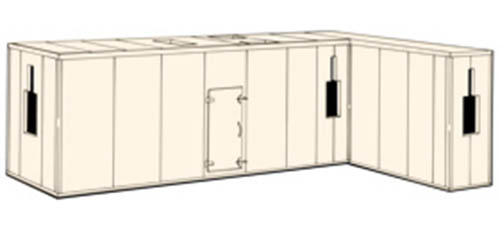
McGill AirSilence's Heatscreen oven enclosures are an excellent choice where the process requires controlled application of heat for baking, drying, or curing. They have low leakage, excellent thermal properties, and a large selection of design options and accessories to meet a customer's specific needs. Applications include designs for the paint finishing, powder coating, food processing, baking, pharmaceutical industries, and others.
Design Features
- The Heatscreen oven panel is designed for internal temperatures up to 600°F. The tongue-and-groove joint allows easy on-site assembly.
- The oven enclosure's roof is designed to vent and relieve excessive internal pressures.
- Enclosures do not exceed the L/200 deflection limit for a 10-foot panel with a 600-pound load applied.
Options
- Pre-hung safety doors
- Glass ceramic windows
- Custom profile cutouts
- Enclosures can be preassembled
- Aluminized steel or stainless steel construction
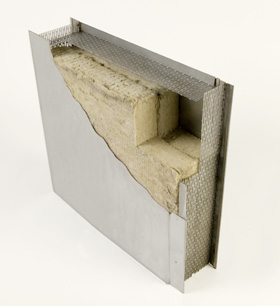
McGill AirSilence Heatscreen™ oven enclosures are constructed from our oven panels that are designed to minimize heat transfer. The standard wall, roof, and floor oven panels consist of a sandwich construction of an outer metal shell, thermal insulating fill, and an inner metal liner. The wall and roof panels are available in 4- or 6-inch thicknesses, 24 inches wide, and up to 10 feet long. Floor panels are 4 inches thick, 24 inches wide, and up to 10 feet long. Wall panels can be manufactured from galvanized (outer shell only), stainless steel, or aluminized steel in 16- through 20-gauge thicknesses. All longitudinal joining channels and internal reinforcing members in Heatscreen oven panels are fabricated from a minimum of 18-gauge steel.
Insulation
The thermal insulating fill used in all standard Heatscreen oven panels is mineral wool insulation. It will not settle or promote the growth of bacteria, mold, vermin, or insects.
Surface Burning Characteristics
All insulating materials, inner and outer surfaces, and sealer used in Heatscreen oven panels and enclosures meet the requirements of NFPA-90A.
Joint Construction
The Heatscreen oven panel features an easy to install slip-fit, tongue-and-groove joint.
Heatscreen™ Panel Assembly
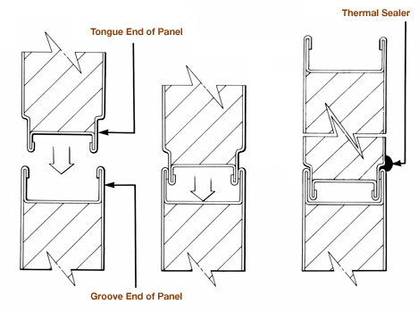
The panel assembly sequence illustrated shows the assembly of the oven panel system. First, a panel is placed in the base made of two angles that allow a thermal break. A second adjoining panel is then placed in the base and aligned with the first panel. The tongue end of the second panel is started in to the groove end of the first panel and maneuvered into place. Top and bottom of the panels are secured mid-span to the trim to allow small thermal expansion to occur at the joint. A bead of non-hardening, thermal sealer is then run along the entire length of the outside surface in the recess formed by the mating of the tongue-and-groove ends of the two panels.
Roof panels are connected with explosion relief screws.
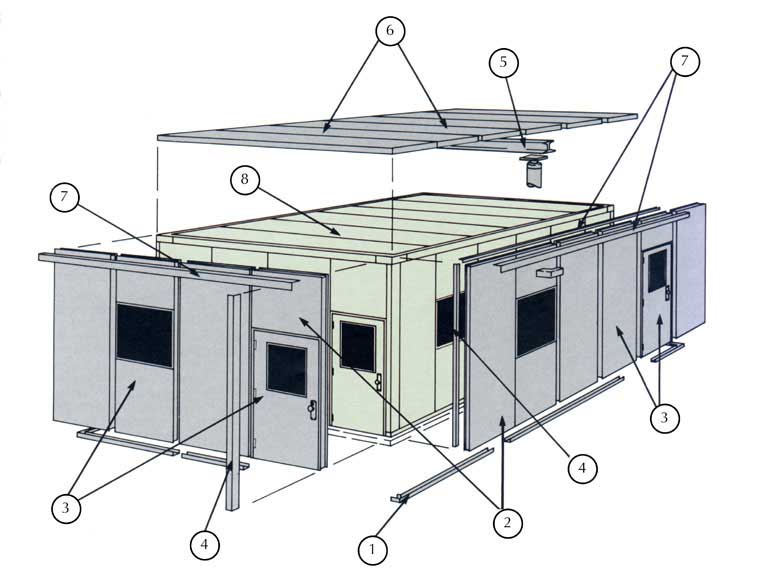
Typical Installation Sequence
- Locate base channel
- Set corner panels
- Install wall, partition, and door panels
- Add wall trim — outside and inside
- Optional structural steel (as required)
- Add roof panels
- Add roof trim — outside and inside
- Completed acoustical enclosure
GENERAL
Double-wall (insulated) panel enclosures shall be provided as specified on drawings. All panels and components shall be prefabricated and supplied by a nationally-recognized manufacturer with published standards of construction, assembly, and technical performance. The manufacturer shall have produced a standardized, prefabricated panel system for at least 10 years. Construction and performance of the installed system and components shall conform to all specifications listed in this document.
JOINT CONSTRUCTION
Enclosure panels shall have a tongue-and-groove joint construction. Panels will be held together with fasteners such as screws installed at the panel/trim connection point at the mid-span of the panel. Panels should not require H-connectors, tape, or any other type of additional connectors.
PANEL CONSTRUCTION
- All enclosure panels shall be 4 or 6 inches thick, as noted on the drawings, with a solid galvanized steel, aluminized steel, or stainless steel exterior shell, and a solid interior aluminized steel or stainless steel shell as noted on the drawings.
- The outer and inner shells shall be tack or spot welded to perimeter and internal longitudinal steel channels and box-end internal closures, in such a manner and spacing that the panel assembly will not fail at the maximum operating loads specified in Structural Performance.
- The outer shell shall be constructed of solid galvanized steel, aluminized steel, or stainless steel with a minimum 16-gauge thickness.
- The inner shell shall be constructed of solid aluminized steel or stainless steel with a minimum 20-gauge thickness.
- All perimeter and internal longitudinal steel channel members shall be constructed of ASTM commercial-quality steel consistent to inner shell material with a minimum 18-gauge thickness.
- All steel panel surfaces, internal channels, and trim items shall be fabricated from materials consistent to the inner and outer shell construction.
- Each enclosure panel shall be completely filled with thermal insulating material that is non-combustible, inert, mildew-resistant, and vermin-proof. Insulation shall not settle within the enclosure panel. No insulating materials shall be used that have a flame spread greater than 25 or a smoke developed greater than 50.
COMPONENTS AND INSTALLATION
- All base angles shall be installed on a level concrete curb, the dimensions of which shall be determined from plan-view shop drawings of the system provided by the system manufacturer. Spacing of base angle attachments shall be as outlined in the manufacturer's standard details of assembly.
- All assembly trim items shall be constructed to match the material of the inner or outer shell dependent on which shell they are to be attached (minimum 18-gauge thickness) and furnished in standard lengths to be field cut to the required dimensions. Spacing of sheet metal screws, application of duct sealant, and positioning of trim shall be in accordance with the manufacturer's published erection and installation details.
- Enclosure joints and trim shall be sealed with McGill AirSeal's Uni-Sil™ HT, which is a one-part, high temperature, 100% silicone sealer formulated to withstand temperatures to 600°F.
- Personnel access doors shall be provided where specified on drawings and shall be 24 inches wide by 60 inches high unless otherwise indicated. All doors shall be the same nominal thickness as the adjacent panels. All access door panels and doors shall be constructed with an 18-gauge solid inner and outer shell. Each door shall have a minimum of two ball-bearing hinges and two wedge-lever door latches or panic/passage hardware. Doors shall seat against silicone or other high-temperature gasket materials, installed around the entire perimeter of the door frame in such a manner that door operation will provide direct compression with no sliding action between the door and gasket.
- Where shown on drawings, access doors shall be furnished with windows, which are composed of double-glazed layers of wire-reinforced tempered glass, separated by an air space, and sealed against air leakage by interior and exterior seals. Windows shall be 12 inches wide by 12 inches high unless otherwise indicated. Inside seals for windows must be able to withstand temperatures of 600°F so silicone or other high-temperature sealers are required.
STRUCTURAL PERFORMANCE
- The entire enclosure shall be designed by the manufacturer to be self-supporting. Where roof spans and wall loadings require additional structural strength, it shall be provided by heavier panel skins, additional internal longitudinal reinforcing members, or additional structural members and necessary supporting pipe columns.
- Under the conditions specified in the previous section, the assembled structure shall not exhibit any panel joint deflections in excess of L/200, where L is the unsupported span length of any panel section within the completed enclosure.